Komunikasi bergerak (mobile communication) mulai dirasakan perlu sejak orang semakin sibuk pergi ke sana kemari dan memerlukan alat telekomunikasi yang siap dipakai sewaktu-waktu di mana saja ia berada. Kebutuhan ini ternyata tidak dibiarkan begitu saja oleh para engineer telekomunikasi. Mereka telah memikirkan standardisasi untuk komunikasi bergerak ini, salah satunya adalah GSM (Global System for Mobile communications)
Alokasi spektrum frekuensi untuk GSM awalnya dilakukan pada tahun 1979. Spektrum ini terdiri atas dua buah sub-band masing-masing sebesar 25MHz, antara 890MHz - 915MHz dan 935MHz - 960MHz. Sebuah sub-band dialokasikan untuk frekuensi uplink dan sub-band yang lain sebagai frekuensi downlink.
Karena konsekuensi logis dari kenaikan redaman atas kenaikan frekuensi, biasanya sub-band terendah dipakai untuk uplink, agar daya yang ditransmisikan oleh MS (mobile system atau lebih dikenal handphone) ke BTS (Base Transmitter Station yaitu seperti sentral telepon di PSTN/POTS, namun memiliki fungsi lebih) tidak perlu besar. Kalau digunakan sub-band yang satu lagi, mungkin anda perlu melakukan recharge batere handphone berulang kali untuk mendapatkan kualitas sama dengan saat ini.
 Kemudian kedua sub-band tersebut dibagi lagi menjadi kanal-kanal, sebuah kanal pada satu sub-band memiliki pasangan dengan sebuah kanal pada sub-band yang lain. Tiap sub-band dibagi menjadi 124 kanal, yang kemudian masing-masing diberi nomor yang dikenal sebagai ARFCN (Absolute Radio Frequency Channel Number). Jadi sebuah MS yang dialokasikan pada sebuah ARFCN akan beroperasi pada satu frekuensi untuk mengirim dan satu frekuensi untuk menerima sinyal.
Untuk GSM, jarak antar pasangan dengan ARFCN sama selalu 45MHz, dan bandwidth tiap kanal sebesar 200kHz. Kanal pada tiap awal sub-band digunakan sebagai guard band. Silakan anda hitung, maka spektrum GSM akan menghasilkan 124 ARFCN, masing-masing diberi nomor 1 sampai 124. Kanal sebanyak 124 inilah yang nantinya dibagi-bagi buat operator-operator GSM yang ada di suatu negara.
Untuk mengantisipai perkembangan jaringan di masa mendatang, telah dilokasikan tambahan 10MHz frekuensi pada masing-masing awal sub-band. Ini dikenal sebagai EGSM (Extended GSM). Jadi spektrum EGSM ini 880MHz - 915MHz buat uplink dan 925MHz - 960MHz buat downlink. Hal tersebut memberi tambahan 50 ARFCN menjadi 174. Tambahan ARFCN ini diberi nomor 975 - 1023.
DCS 1800
Seiring dengan evolusi GSM, diputuskan untuk menerapkan teknologi ini pada PCN (Personal Communication Networks). Hal ini membutuhkan perubahan pada interafce udara untuk memodifikasi frekuensi operasinya. Frekuensi modifikasinya antara 1710MHz - 1785MHz untuk uplink dan 1805MHz - 1880MHz untuk downlink. Teknik ini menyediakan 374 ARFCN dengan pemisahan frekuensi sebesar 95MHz antara uplink dan downlink.
Teknik PCN ini dikembangkan di Eropa, khususnya di Inggris. Di Inggris (Raya) ARFCN ini telah dibagi-bagi antara keempat operator jaringan yang ada di sana. Dua di antaranya, Orange dan One to One, beroperasi pada daerah GSM 1800, sementara dua yang lainnya, Vodafone dan Cellnet, telah dialokasikan kanal GSM 1800 pada puncak jaringan GSM 900 mereka. ARFCN ini diberi nomor 512 - 885. Porsi pada puncak band digunakan oleh DECTs (Digital Enhanced Cordless Telephony).
PCS 1900
PCS 1900 merupakan adaptasi GSM yang lain ke dalam band 1900MHz. Teknik ini digunakan di Amerika Serikat di mana FCC (Federal Communication Commission) telah membaginya menjadi 300 ARFCN dan mengumumkan lisensi pada berbagai macam operator untuk mengimplementasikan jaringan GSM. Pemisahan frekuensinya sebesar 80MHz, dan pembagian frekuensinya adalah 1850MHz - 1910MHz untuk uplink dan 1930MHz - 1990MHz untuk downlink.
Teknik Modulasi dan Bandwidth
Teknik modulasi yang digunakan pada GSM adalah GMSK (Gaussian Minimum Shift Keying). Teknik ini bekerja dengan melewatkan data yang akan dimodulasikan melalui Filter Gaussian. Filter ini menghilangkan sinyal-sinyal harmonik dari gelombang pulsa data dan menghasilkan bentuk yang lebih bulat pada ujung-ujungnya. Jika hasil ini diaplikasikan pada modulator fasa, hasil yang didapat adalah bentuk envelope yang termodifikasi (ada sinyal pembawa). Bandwidth envelope ini lebih sempit dibandingkan dengan data yang tidak dilewatkan pada filter gaussian.
Bandwidth yang dialokasikan untuk tiap frekuensi pembawa pada GSM adalah sebesar 200kHz. Pada kenyataannya, bandwidth sinyal tersebut lebih besar dari 200kHz, bahkan setelah dilakukan pemfilteran gaussian pun hal itu tetap terjadi. Akibatnya sinyal akan memasuki kanal-kanal di sebelahnya. Jika pada satu sel (akan dijelaskan kemudian) terdapat BTS dengan frekuensi pembawa yang sama atau bersebelahan kanal, maka akan terjadi interferensi akibat overlapping tersebut. Begitu juga jika sel-sel yang bersebelahan memiliki frekuensi pembawa sama atau berdekatan. Alasan inilah yang menyebabkan mengapa dalam satu sel atau antara sel-sel yang berdekatan tidak boleh menggunakan kanal yang sama atau berdekatan.
Pembagian Sel
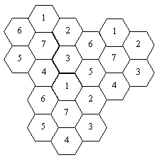
Pembagian area dalam kumpulan sel-sel merupakan prinsip penting GSM sebagai sistem telekomunikasi selular. Sel-sel tersebut dimodelkan sebagai bentuk heksagonal seperti pada gambar berikut. Tiap sel mengacu pada satu frekuensi pembawa / kanal / ARFCN tertentu. Pada kenyataannya jumlah kanal yang dialokasikan terbatas, sementara jumlah sel bisa saja berjumlah sangat banyak. Untuk memenuhi hal ini, dilakukan teknik pengulangan frekuensi (frequency re-use). Pada gambar terlihat contoh frequency re-use dengan jumlah kanal 7 buah. Antara sel-sel yang berdekatan frekuensi yang digunakan tidak boleh bersebelahan kanal atau bahkan sama.
Jelas bahwa semakin besar jumlah himpunan kanal, semakin sedikit jumlah kanal tersedia per sel dan oleh karenanya kapasitas sistem menurun. Namun, peningkatan jumlah himpunan kanal menyebabkan jarak antara sel yang berdekatan kanal semakin jauh, dan ini mengurangi resiko terjadi interferensi. Sekali lagi, desain sistem GSM memerlukan kompromi antara kualitas dan kapasitas.
 Pada kenyataannya, model satu sel dengan satu kanal transceiver (TRx, tentunya menggunakan antena omni-directional) jarang digunakan. Untuk lebih meningkatkan kapasitas dan kualitas, desainer melakukan teknik sektorisasi. Prinsip dasar sektorisasi ini adalah membagi sel menjadi beberapa bagian (biasanya 3 atau 6 bagian; dikenal dengan sektorisasi 120o atau 30o). Tiap bagian ini kemudian menjadi sebuah BTS (Base Transceiver Station). Kebanyakan vendor memperbolehkan sampai dengan 4 TRx per BTS untuk sektorisasi 120o. Jika digunakan TDMA pada TRx, menghasilkan 8 kanal TDMA tiap TRx, Anda bisa menghitung bahwa dalam satu sel dapat menampung trafik yang setara dengan 3 X 4 X 8 = 96 kanal TDMA atau sebesar 82,42 erlang dengan GoS 2%. (Erlang merupakan satuan trafik dan GoS(Grade of Service) menyatakan derajat keandalan layanan, berapa jumlah blocking yang terjadi terhadap panggilan total)
Pada prakteknya tidak semua kanal TDMA tersebut bisa digunakan untuk kanal pembicaraan (TCH = Traffic Channel). Dalam sebuah BTS juga diperlukan SDCCH (Stand-alone Dedicated Control Channel) yang digunakan untuk call setup dan location updating serta BCCH (Broadcast Control Channel) yang merupakan kanal downlink yang memberikan informasi dari BTS ke MS mengenai jaringan, sel yang kedatangan panggilan, dan sel-sel di sekitarnya.
Struktur Sistem Selular
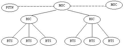
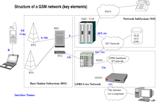
Bagian paling rendah dari sistem GSM adalah MS (Mobile Station). Bagian ini berada pada tingkat pelanggan dan portable. Pada tiap sel terdapat BTS (Base Transceiver Station). BTS ini fungsinya sebagai stasiun penghubung dengan MS. Jadi, merupakan sistem yang langsung berhubungan dengan handphone Anda.
BTS pada dasarnya hanya merupakan "pesuruh" saja. Otak yang mengatur lalu-lintas trafik di BTS adalah BSC (Base Station Controller). Location Updating, penentuan BTS dan proses handover pada percakapan ditentukan oleh BSC ini. Beberapa BTS pada satu region diatur oleh sebuah BSC.
BSC-BSC ini dihubungkan dengan MSC (Mobile Switching Center). MSC merupakan pusat penyambungan yang mengatur jalur hubungan antar BSC maupun antara BSC dan jenis layanan telekomunikasi lain (PSTN, operator GSM lain, AMPS, dll).Saat ini teknik switching terus berkembang, dan begitu pula pada layanan GSM. Beberapa operator GSM di Indonesia telah menerapkan Intelegent Network lanjutan dalam teknik switchingnya.
Frequency Hopping
Frequency hopping merupakan fitur yang diterapkan pada interface udara, yakni lintasan radio ke MS. Teknik ini dapat mengurangi redaman akibat efek multipath fading. GSM hanya merekomendasikan satu jenis frequency hopping, yakni baseband hopping. Namun beberapa vendor, seperti Motorola, menyediakan tipe frequency hopping yang lain, yang disebut Synthesizer Hopping.
Baseband Hopping digunakan jika base station memiliki beberapa DRCU/TCU tersedia. Aliran data secara sederhana dilalukan pada frekuensi dasar ke berbagai macam DRCU/TCU. Setiap data beroperasi pada frekuensi yang tetap, mengacu pada urutan hopping yang ditentukan. DRCU/TCU yang berbeda akan menerima sebuah timeslot yang spesifik pada setiap frame TDMA, berisi informasi yang ditujukan kepada MS-MS yang berbeda.
Synthesizer Hopping menggunakan kelincahan ferkuensi dari DRCU/TCU untuk mengubah frekuensi-frekuensi pada sebuah basis timeslot untuk transmisi maupun menerima. SCB pada DRCU serta sistem kontrol dan pemrosesan digital pada TCU akan menghitung dan menentukan frekuensi selanjutnya, dan memprogram sebuah pasangan synthesizer Tx dan Rx untuk menuju ke frekuensi yang telah dihitung.
Teknik synthesizer hopping ini sangat baik untuk diterapkan pada sel-sel dengan jumlah carrier yang sedikit. Untuk sel-sel dengan jumlah carrier yang banyak, teknik baseband hopping merupakan teknik yang paling baik. Dan kedua teknik ini tidak bisa diterapkan sekaligus pada sebuah site BTS.
Sumber : http://cahbuton.tripod.com/id16.html


 Kemudian kedua sub-band tersebut dibagi lagi menjadi kanal-kanal, sebuah kanal pada satu sub-band memiliki pasangan dengan sebuah kanal pada sub-band yang lain. Tiap sub-band dibagi menjadi 124 kanal, yang kemudian masing-masing diberi nomor yang dikenal sebagai ARFCN (Absolute Radio Frequency Channel Number). Jadi sebuah MS yang dialokasikan pada sebuah ARFCN akan beroperasi pada satu frekuensi untuk mengirim dan satu frekuensi untuk menerima sinyal.